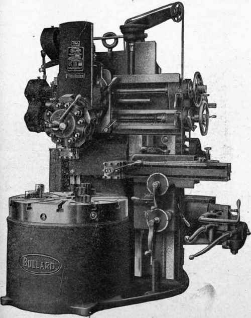
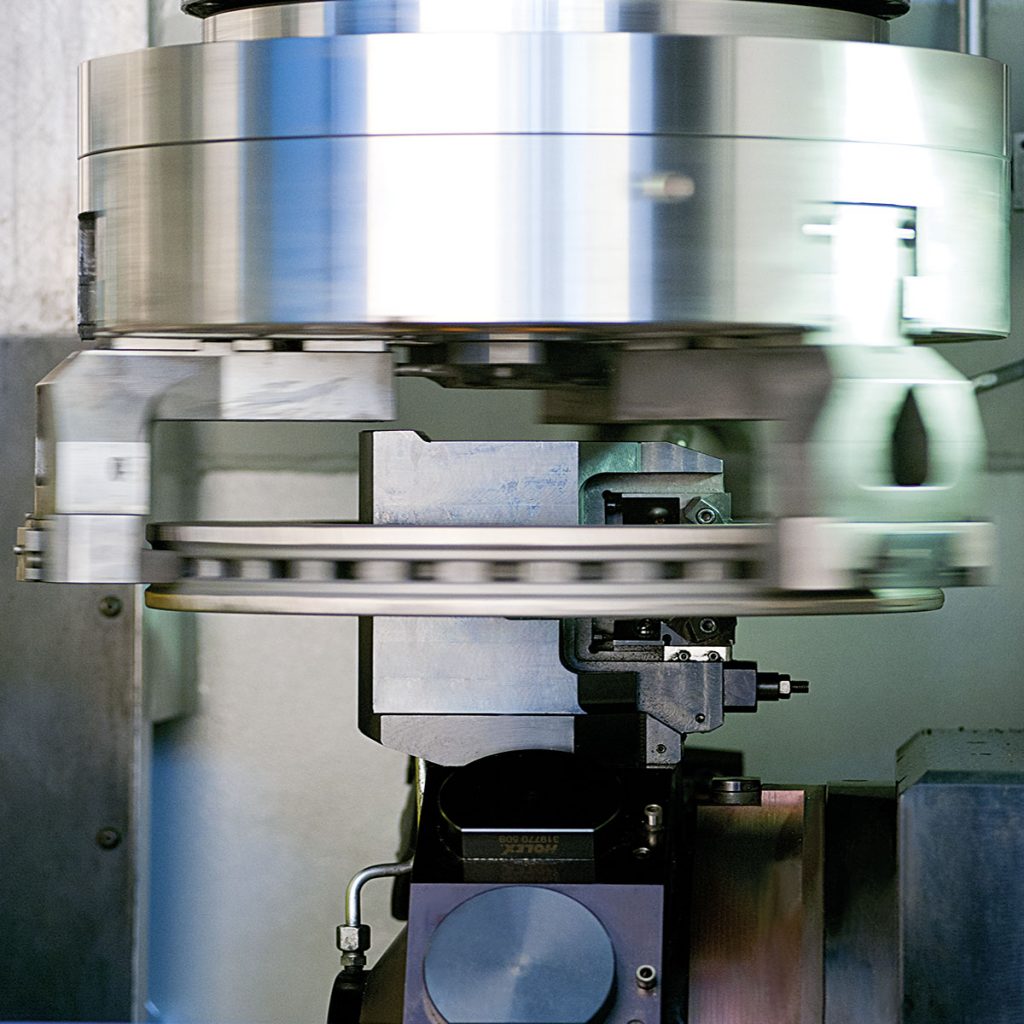
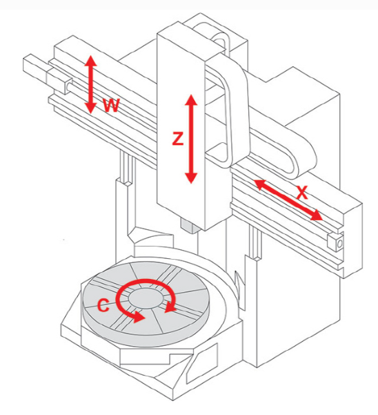
The machine shown in the above image is Bullard Vertical Turret Lathe, produced approximately 100 years ago at Bullard Machine Tool Company (Bridgeport, Connecticut, USA). It an ancient vertical lathe.
The table rotates below, with a turret for selecting tools and a handle for moving the turret horizontally and vertically. This type of machine can make cylindrical parts.
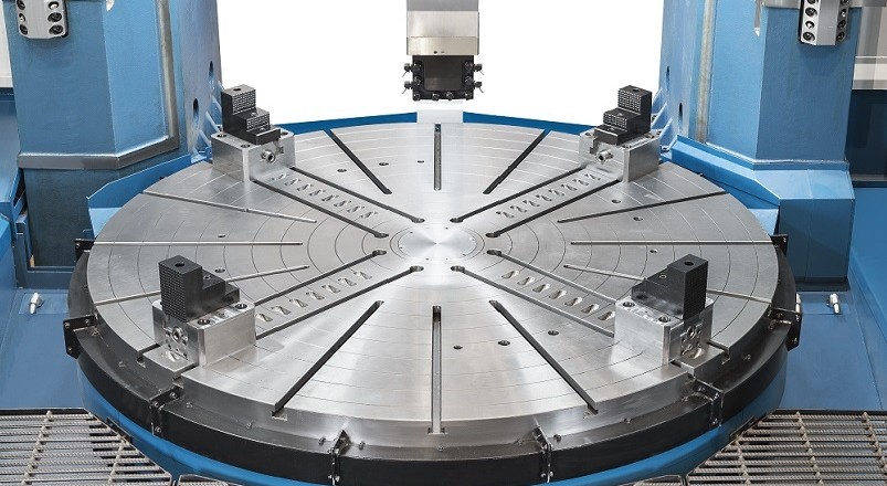
Take a look at the next photo.
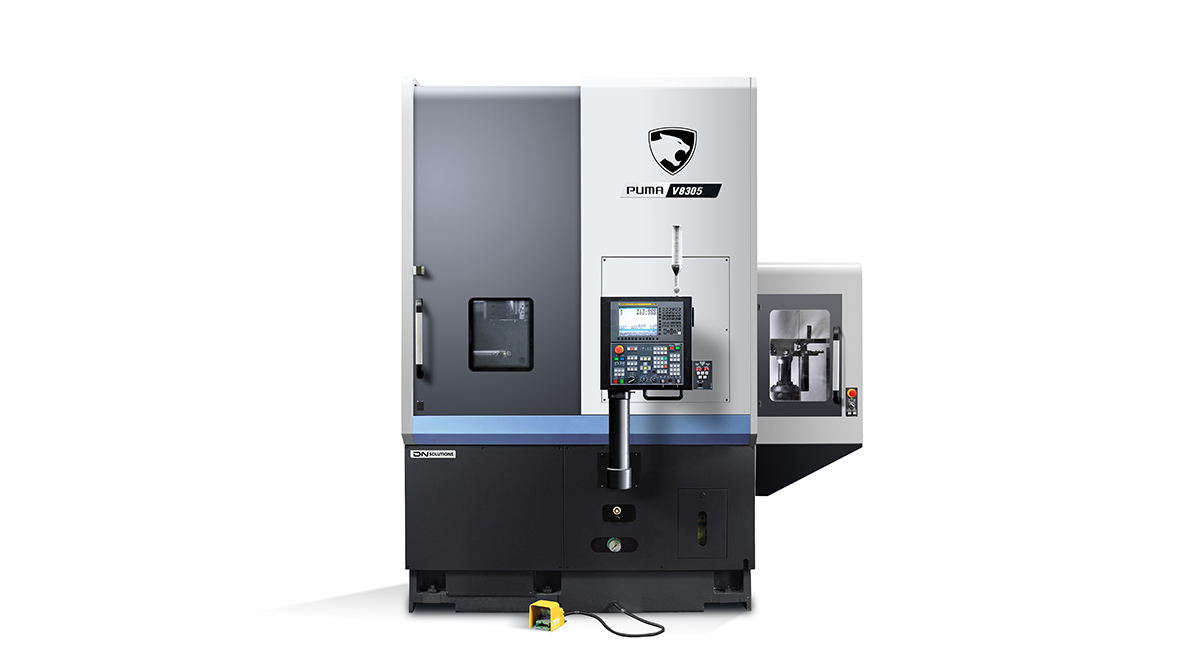
The machine in this photo is the latest appearance of vertical lathes. Above is the appearance of the machine, below is the interior, which is DN Solutions' PUMA V8305.
These machines are also known as vertical lathes as before, but today vertical turning centers are common. But the functionality is actually the same as the previous machines. That is to say, perform a machining process called turning. For the workpiece hold on the turning spindle, by moving the turning tool on a plane surface, the desired shape is created through cutting the workpiece. The final shape of workpieces is cylindrical.
Then what's the differences?
Firstly, the appearance has changed. There is a cover that isolats it from the outside of the machine, a safety door is set up. Turning centers are not manually operated by the operator, but by the computer according to a pre-entered program. Therefore, the machining space needs to be completely separated from the outside for safety.
Secondly, as mentioned earlier, the computer is installed on the machine. Computers participate in machine action and status monitoring, as well as signal processing from to outside.
At first glance, it seems that there have been significant changes, but the working methods have changed, the processing quality has been leveled up, and work efficiency has been improved, but there has been no fundamental change. But why use the name of the turning center instead of the lathe?
Turning means a cutting process that takes place while the workpiece rotates with fixed tool. Then what does the center mean? The center refers to the comprehensive implementation in one place. Shopping centers, car care centers, and other facilities are also used around us. If you look at DN Solutions PUMA VT8305, the meaning of turning Center is a bit unnatural because this machine is most simple form of turning centers.
In fact, there are other reasons for using the term 'vertical turning center'. Now let's get to know more.
The number of available tools is an important factor in the machining process.
Gang is a plate of arranging the required tools in a row. Usually, 4 to 6 tools can be placed. The selection of tools is controlled by the X-axis, so the X-axis usually becomes longer than other types of machines.
Turret is a method of placing the tool on the surface and side of a flat cylindrical shape, and dividing it to select the tool.
The tool holders used for turret usually adopts three methods:
Hydraulically or Numerically operated, it is designed for facing two opposing planes “in one shot.” At process completion, the upper insert detaches allowing retraction from the workpiece.
자료출처: Famar ERGO
On the vertical turning center, in some machines a ram is attached and equipped with a tool post, a tool clamping mechanism for tool holders of turning or milling at its end.
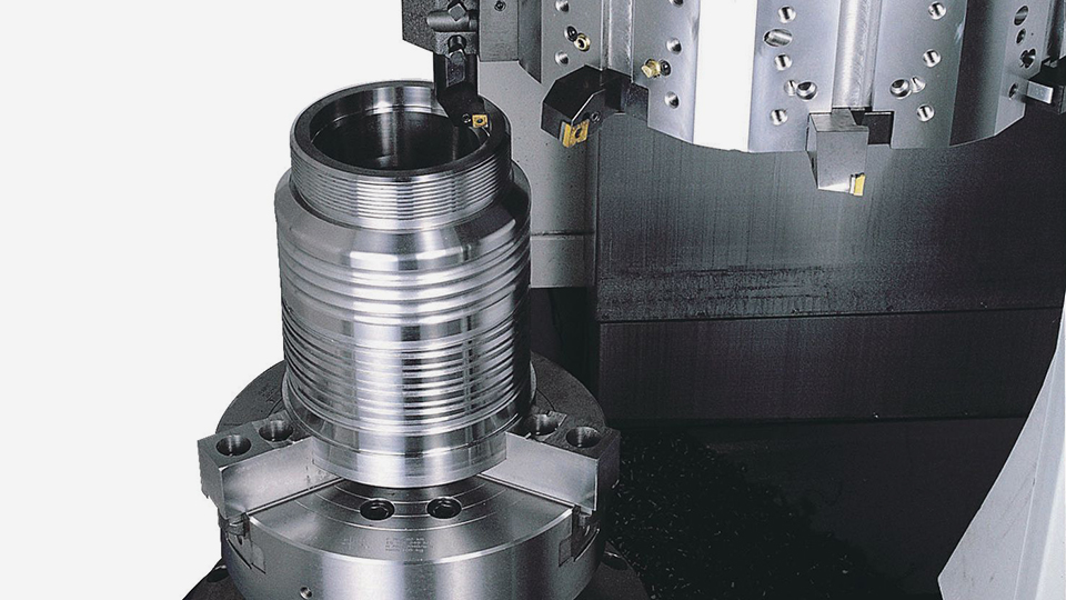
A chuck is mounted on turning spindles. Chucks hold and rotate a workpiece.
source: ROMI VT 2500M
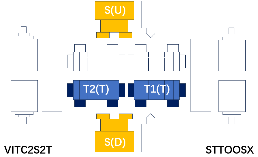
We have viewed the components of vertical turning centers above and can merge them into the following diagram.
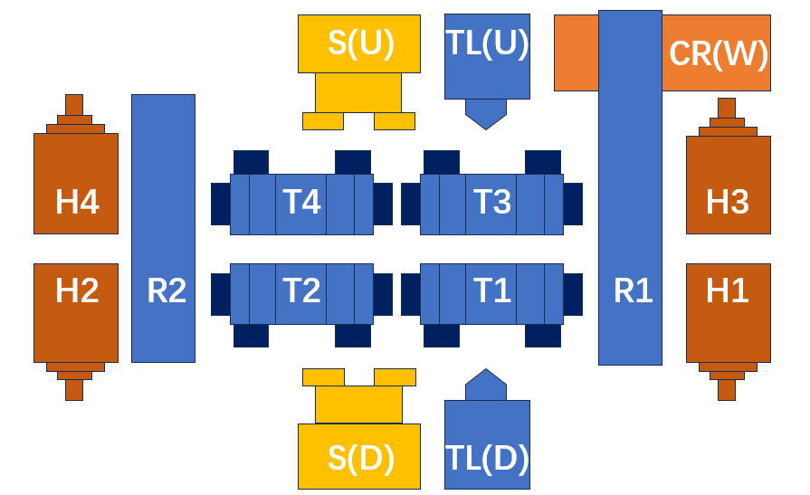
S(U): Turning spindle(Upper)
S(L): Turning spindle(Lower)
H1: #1 Milling spindle #1
H2: #2 Milling spindle #2
H3: #3 Milling spindle #3
H4: #4 Milling spindle #4
T1: Tool post #1
T2: Tool post #2
T3: Tool post #3
T4: Tool post #4
TL(U): Tail stock(Upper)
TL(L): Tail stock(Lower)
R1: Ram #1
R2: Ram #2
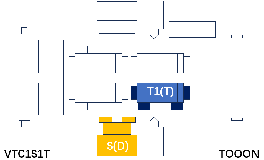
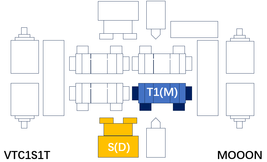
Let's take a look at the system diagram of vertical turning center again.
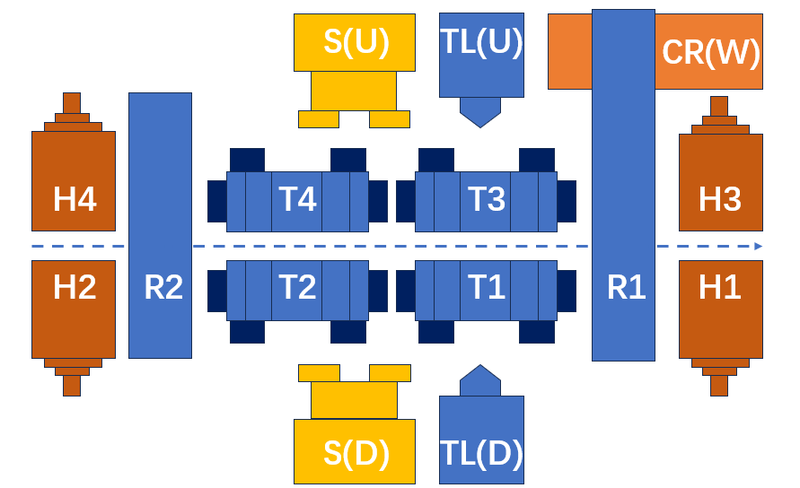
Based on the dashed line in the middle, the lower part is called a vertical turn center (VTC), and the upper part inverted vertical turn center (IVTC). If both the upper and lower parts exist, it is called a vertical & inverted vertical turning center (VIVTC).
So from now on, let's take a look at the types of vertical rotation centers.
This is like a vertical version of two axis gang-type horizontal turning center without tail stock.
source: Berthiez TVU 1400/80
The small and medium-sized vertical turning center can be configured with two machines symmetrically left and right. The reason for using left and right symmetry is that the distance between the two main axes can be minimized, reducing the transfer time of the workpiece between the two machines.
The left and right machines should be the same size, but their functions may be different. For example, the machine on the right only has turning function, while the machine on the left can mount rotating tools to give milling function.
Due to moving units like gang, turret and ram on the upper part of the machine, it is difficult to place workpiece transport devices like gantry robot on the upper part of the machine. Therefore, industrial robots are commonly used.
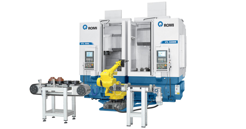
source: ROMI VTL 500
Inverted vertical turning center spindle moves in the upper part, and the spindle itself can be used as a workpiece handling device. Usually, automation can be achieved by installing a device on the left side of the machine that can place workpieces.
In VIVTC, the upper spindle can be used as a workpiece handling device, and the lower spindle can turn all processes left.
3.1 (VTC) 1 TS 1 Gang
| No. | Chuck size(S1) | Workpiece length | button |
| No. | Chuck size(S1) | Workpiece length | button |
| No. | Chuck size(S1) | Workpiece length | button |
3.2 (VTC) 1 TS 1 Turret
| No. | Chuck size(S1) | Workpiece length | button |
| 1 | 12 | All | SUBMIT |
| 2 | 15 | All | SUBMIT |
| 3 | 18 | All | SUBMIT |
| 4 | 21 | All | SUBMIT |
| 5 | 32 | All | SUBMIT |
| 6 | 40 | All | SUBMIT |
| No. | Chuck size(S1) | Workpiece length | button |
| 1 | 12 | All | SUBMIT |
| 2 | 15 | All | SUBMIT |
| 3 | 18 | All | SUBMIT |
| 4 | 21 | All | SUBMIT |
| 5 | 32 | All | SUBMIT |
| 6 | 40 | All | SUBMIT |
| No. | Chuck size(S1) | Workpiece length | button |
3.3 (VTC) 1 TS 2 Turret
| No. | Chuck size(S1) | Workpiece length | button |
| No. | Chuck size(S1) | Workpiece length | button |
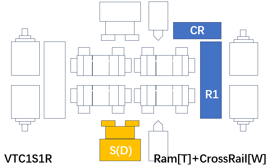
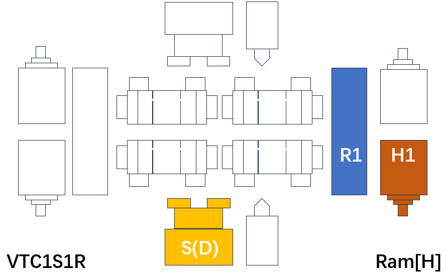
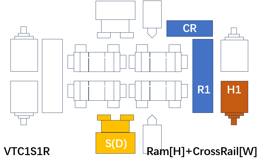
3.4 (VTC) 1 TS 1 Ram
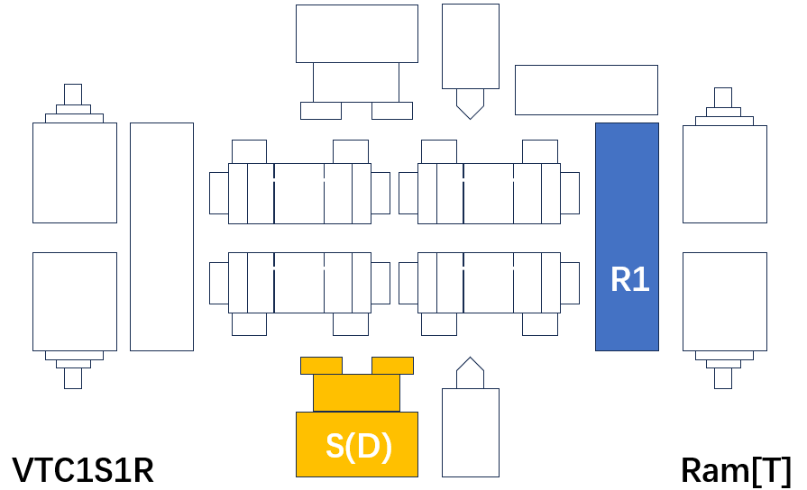
| No. | Chuck size(S1) | Workpiece length | button |
| 1 | 40 | All | SUBMIT |
| 2 | 45 | All | SUBMIT |
| 3 | 50 | All | SUBMIT |
| 4 | 55 | All | SUBMIT |
| 5 | 63 | All | SUBMIT |
| 6 | 70 | All | SUBMIT |
| 7 | 80 | All | SUBMIT |
| 8 | 100 | All | SUBMIT |
| No. | Chuck size(S1) | Workpiece length | button |
| 1 | 40 | All | SUBMIT |
| 2 | 45 | All | SUBMIT |
| 3 | 50 | All | SUBMIT |
| 4 | 55 | All | SUBMIT |
| 5 | 63 | All | SUBMIT |
| 6 | 70 | All | SUBMIT |
| 7 | 80 | All | SUBMIT |
| 8 | 100 | All | SUBMIT |
| No. | Chuck size(S1) | Workpiece length | button |
| 1 | 40 | All | SUBMIT |
| 2 | 45 | All | SUBMIT |
| 3 | 50 | All | SUBMIT |
| 4 | 55 | All | SUBMIT |
| 5 | 63 | All | SUBMIT |
| 6 | 70 | All | SUBMIT |
| 7 | 80 | All | SUBMIT |
| 8 | 100 | All | SUBMIT |
| No. | Chuck size(S1) | Workpiece length | button |
| 1 | 40 | All | SUBMIT |
| 2 | 45 | All | SUBMIT |
| 3 | 50 | All | SUBMIT |
| 4 | 55 | All | SUBMIT |
| 5 | 63 | All | SUBMIT |
| 6 | 70 | All | SUBMIT |
| 7 | 80 | All | SUBMIT |
| 8 | 100 | All | SUBMIT |
3.5 (VTC) Vertical and Inverted VTC (2 TS+2 Turret)